|
Which Chipmunk Is That?
by Rod Blievers

HyperScale is proudly supported by Squadron
This humble little aeroplane has been around for a very long time, and has become the subject of many myths and misconceptions.
It appears that very few are aware of just how different the Canadian-built Chipmunks were from their UK (and Portuguese) built brethren. It needs to be stressed that a Canadian-built Chipmunk is not just a UK-built Chipmunk with a different canopy! That's despite what Airfix and other "informed" observers seem to think. There were many structural differences; different gauge metal was used, differently designed sub-systems, different equipment fitted - to the point that most components were not even interchangeable!
There are three basic sub-types; the Canadian-built examples comprise either the DHC-1A or the DHC-1B, while in the UK (and Portugal) production were of the visually indistinguishable Chipmunk T.10/Mk.20/Mk.21/Mk.22 series. I will concentrate on what this means to modellers, and attempt to highlight the external differences/features between the three.
DHC-1A
This was the first version to appear, built mainly as the DHC-1A-1 with a handful of DHC-1A-2 models appearing at the end of the production run. Arguably the true Tiger Moth replacement, this was a rather simple and “lightweight” aircraft produced in rather modest numbers (62). Indeed, but for interest in the RAF's Tiger Moth replacement, one rather suspects that the Chipmunk story might have ended right here! The DHC-1A was allegedly the sweetest handling Chipmunk of them all - given the type's reputation for superb handling, that's really saying something!
Features include:
-
Fitted with dual elevator trim tabs (first 21 aircraft built only), then subsequently on the RH elevator only. See Photo 4.
-
Narrow chord rudder (subtly less curved trailing edge, no "kink" at the lower trailing edge). See Photo 4.
-
External bracing strips on the upper tail cone behind the rudder. See Photo 3.
-
Hole for the lifting rod located aft of the frame line on rear fuselage. See Photo 7.
-
No battery access panels on the fuselage (indeed until the advent of the DHC-1A-2 no electrical system at all). See Photo 7.
-
Narrow cross-section windscreen with straight profile at lower edge (when viewed from the side) – see Photo 1.
-
Canopy thinly framed, without the bulged rear side panels, access handles are positioned on canopy centre-line plus two side-screen release latches on the RHS, fitted on lower edge, central to each panel. See Photo1, although the side-panel latches aren’t fitted to this restoration.
-
Canopy slides on recessed “channels” on the fuselage side, the recess for this is apparent at rear of canopy even when it's slid fully forward (i.e. when it’s closed). See Photo 5.
-
Fuselage frame doubler immediately aft of cockpit has an additional elongated “V”-shaped plate applied over it (parallel to direction of flight) – Photo 5 again.
-
Simplified instrument panels without an artificial horizon or directional gyro, straight-edged coamings with no overhang of the panels. Prominent (magneto) switches on the coaming LHS (both cockpits). See Photo 2.
-
Bottom of cowlings in line with fuselage (viewed from side, i.e. no "step"), one intake on LHS.
-
Vertical slot in centre of front cowling. See Photo 8.
-
Spinner has a panel line at half chord. See Photo 8.
-
Exhaust emerges from slot in RH cowl at a shallow angle, has a kinked end. See Photo 1.
-
Undercarriage legs mounted virtually perpendicular to wing surface, sometimes fitted with short chord fairings. See the fuller explanation in the UK-built section. See Photo 1.
-
A venturi tube under RH front cockpit. See Photo 1.
-
No navigation or landing lights.
-
Tall "L" shaped pitot mast. See Photo 1.
- Fuel gauge/filler cap assembly is both simple and streamlined. Cap has central full-diameter finger handle while the gauge is inboard. Fuel vent mast located outboard of the cap/gauge. See Photo 6 & 7.
However on the DHC-1A-2, the engine supported a generator (electrical system) and a vacuum pump (for a full blind-flying panel). These aircraft lacked the venturii and had navigation lights fitted (on the wingtip at 1/3rd chord). These aircraft also had a circular connector plug immediately aft of the firewall on the LHS (similar to UK-built Chipmunks).
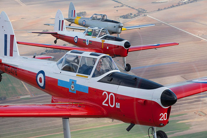
Photo 1. VH-MCC is not only the one DHC-1A-1 remaining in Australia but also the very first Chipmunk to arrive here (in 1947). It has been faithfully restored, although neither the spinner or some canopy details are original (no side panel latches). The top cowling scoop is also a modern addition (no Canadian-built Chipmunk had this intake when they left the factory). Note the venturi tube, the straight horizontal lower edge to the windscreen, thin canopy framing, flat rear side panel, the kinked exhaust, “L” shaped pitot and the more vertical angle of the undercarriage legs.
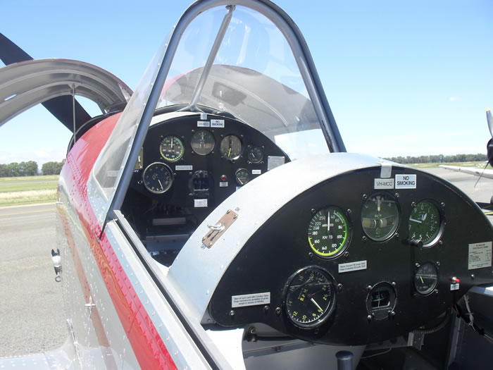
Photo 2. The narrower “pointy” topped canopy cross-section is apparent here (compare with Photo 10), note also the simplified instrument panel layout, prominent ignition switches on the coaming LHS (fitted to both cockpits; the frame here hides those for the forward cockpit) and just how narrow the coaming seems - it doesn't overhang the instrument panel.
Photo 3. External bracing strips on the tail cone. This is a DHC-1A-2 and has only the single elevator trim tab. Note the “blunt” end to the tailcone.
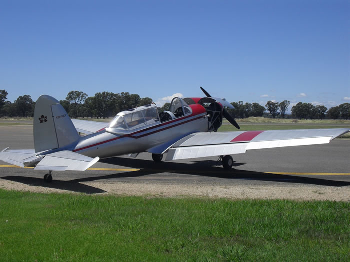
Photo 4. Just visible here are the dual elevator trim tabs (discontinued after the 21st aircraft) plus the narrow-chord rudder, which has a less sweeping trailing edge – the most obvious visual clue is that it lacks the “kink” at the bottom of the trailing edge. Compare the thinner elevator horns with those fitted to UK-built Chipmunks – Photo 22.
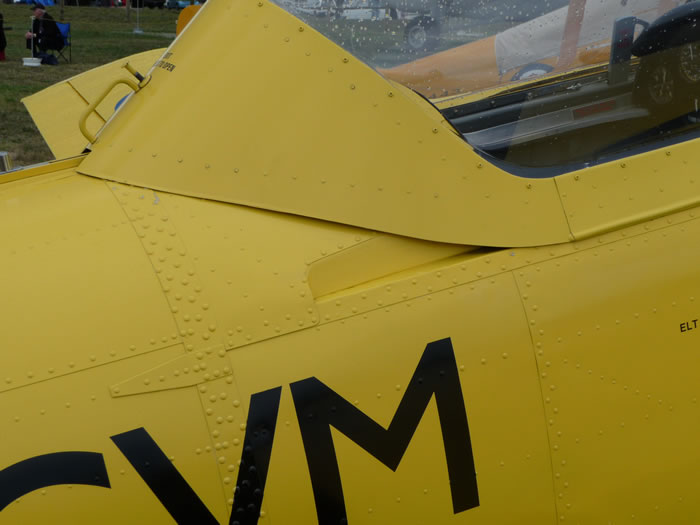
Photo 5. The deep canopy side rail channel is visible when the canopy is slid fully forward. Note also the panel applied over, and at right angles to, the fuselage frame doubler (directly above the letter “V”). The blown canopy is a retrofit item and thus spurious on this particular aircraft; it’s from a DHC-1B-2-S3.
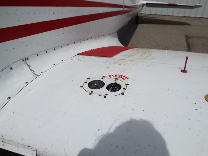
Photo 6. Note the outboard of the red-painted fuel vent mast; the central raised bar on the cap and the generally flush appearance.
DHC-1B
This was a much more capable and better equipped version of the Chipmunk. It had a stronger centre-section, thus removing the weight/aerobatic restrictions that limited the DHC-1A. 155 were built.
The initial batch, DHC-1B-2-S1's and S2's, were built for export and looked very much like the DHC-1A-2. These are the most elusive Chipmunks of them all; only 38 were built and all exported to far way places (Egypt, Lebanon and Thailand). Reference photos are very limited and are nearly all of museum examples (with all the inherent dangers; certainly the Thai exhibit uses components from different model Chipmunks).The differences were:
-
Broad-chord rudder fitted on production (has a more sweeping trailing edge and a distinct kink where this joins the fuselage).
- Canopy has heavier/clumpier frames, jettison panels now on the RHS with handles at the aft lower edge of both panels.
A subsequent, far more numerous batch were designated DHC-1B-2-S3s and were primarily for the Canadian Dept of Defence for issue to various Canadian aero clubs. The final batch, which incorporated some changes from -2-S3's, was the DHC-1B-2-S5 built specifically for the RCAF. These, in 1956, were the last Chipmunks produced anywhere. Just to add to the confusion, the –S5’s were sometimes referred to as Chipmunk T.30’s when in RCAF service. Both of these sub-types were quite different aircraft – while they’re instantly recognizable by that gorgeous blown canopy, there were numerous other changes:
-
Broad chord rudder - more curved trailing edge, "kinked" at bottom. See Photo 9.
-
Re-enforced mounting base for whip aerial on dorsal spine. See Photo 7
-
Large one-piece "blown" canopy, although the windscreen remained identical to the DHC-1A.
-
Revised instrument layout with a full set of blind flying instruments incorporating "eyebrow" lighting, the coaming now overlaps the instrument panel slightly but still straight edged. Electrical switch panel mounted on the front cockpit coaming. See Photo 7. Also the first aid kit was in a box on rear fuselage decking immediately behind aft cockpit (i.e. inside the canopy). See Photo 11.
-
External power access hatch on LH fuselage side, centrally below cockpit. See Photo 7. This replaced the circular fitting immediately behind the firewall.
-
Deeper cowling, distinctly stepped below the fuselage, with a second air scoop on the lower LHS. See Photos 6, 7 & 9.
-
Tube intake on lower RHS of front cowling combined with a larger diameter exhaust pipe which now emerges almost vertically from rear of the cowl (this change was to accommodate a cockpit heater). See Photos 8 & 9.
-
Undercarriage legs were never faired. See Photo 6.
-
Retractable landing lights under the LH wing. See Photo 6.
-
More angular "pointy" elevator horns, increasing the tailplane span. See Photo 7. It’s possible that this only appeared on the last 60 DHC-1B-2-S5’s built for the RCAF.
-
Stalling strip on inboard wing leading edge reduced in length by 2/3rds. See Photo 8.
-
Air scoop, for cockpit cooling air, located on RHS below the rear cockpit (only on the -S5). See Photo 9.
-
External upper tailcone bracing strips of the DHC-1A replaced by pressed longitudinal "ribs" on the cone upper (flat) surface.
-
There's an additional panel attached to the lower forward cowl which extends the large intake forward overall, but particularly on the outboard edge (and lower lip), so that viewed from the front quarter the intake appears parallel-sided. Viewed from the side the profile below the spinner is subtly more vertical too. In some light conditions the changed profile aft of the intake/ahead of the hinged side panel is apparent. See Photos 6 & 13.
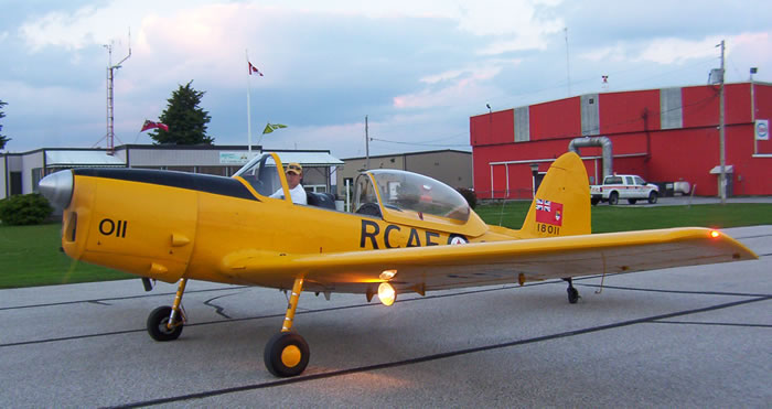
Photo 7. My friend Hugh Shield’s DHC-1B-2-S5 in all its yellow glory. Apparent here is the deeper cowl with the second airscoop low down on the LHS, the lack of the top scoop and the (extended) retractable lading light. The pitot here is distinctly non-standard! The windscreen is identical to that of the DHC-1A. If you look closely, the "lip" around the large nose air intake, giving it a parallel-sided look from this angle, is apparent - see photos 13 & 22.
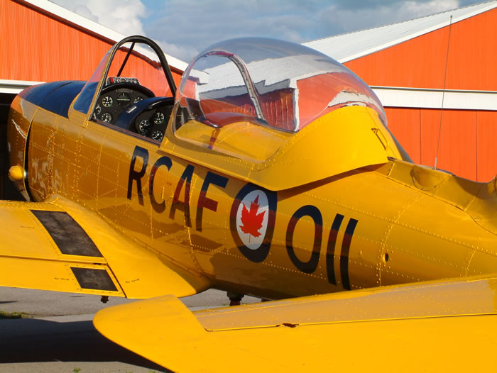
Photo 8. Note here the very pointy elevator horn which effectively extends the tailplane span (this aircraft is a DHC-1B-2-S5), the mounting for the whip antennae on the dorsal spine and the hole for the lifting tube aft of the panel line. The access hatch for ground power is just visible between the “C” and “A” of the RCAF titling. In the cockpit can be seen the switch panel on the forward coaming and more sophisticated instrumentation. While the coaming remains straight-edged, it now appears deeper as it overlaps the instrument panel by a few inches.
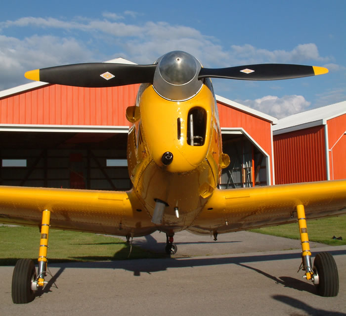
Photo 9. Nose details – here you can see the two-piece spinner, the vertical cooling slot on the centre of the cowl (common to all Canadian-built Chipmunks, not just the DHC-1B), the tubular (heater) intake on the lower RHS (of the aircraft), the near-vertical exhaust stack and the second air scoop on the lower LHS. Note too the shortened stalling strips on the extreme inboard of the wing leading edge and the unfaired undercarriage legs. Obvious here too is the often overlooked distinct “gull wing” effect.
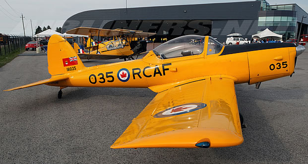
Photo 10. Again the deeper stepped cowl is apparent in this view. Note also the nav light position (common to the DHC-1A-2 and all DHC-1B’s), the cooling air scoop below the rear cockpit (-S5 only) and the “kink” at the base of the broad-chord rudder.
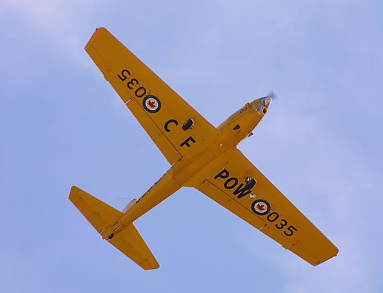
Photo 11. A rare underside view of an ex-RCAF -S5. Many often overlooked items are obvious here; the "pointy" elevator horns, retractable landing light under the left wing, plus the lack of both the downward ID lamp and ventral NACA airscoop.
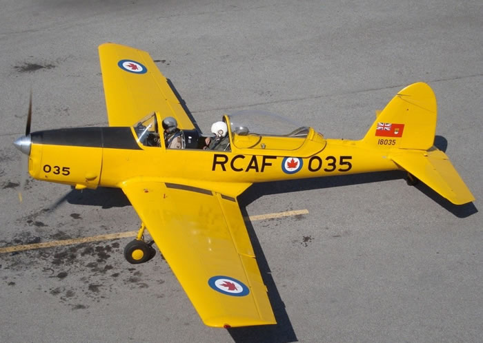
Photo12. A "Chipmunk T.30"; visible here are those "pointy" elevators (again), the first aid kit (grey box) stowed on the fuselage deck immediately behind the rear occupant and the ribbed upper surface of the tailcone.
Photo 13 A DHC-1A photographed parked between two UK-built T.10's - the different undercarriage rake is obvious!
Photo 14 Another good view of the DHC-1B nose. The engine is cowled with six panels; four of them are different from those of UK-built examples!
Chipmunk T.10/Mk.20/Mk.21/Mk.22
These were developed from two DHC-1A’s that were subsequently re-worked in the UK to meet RAF requirements; they were more or less a parallel development of the DHC-1B. They were built in far great numbers (1000 in the UK; 66 in Portugal) than across the Atlantic. The T.10 was built specifically for the RAF, the Mk.20 was the export version of the T.10, the handful of Mk.21’s were built “from the ground up” as civil aircraft while the Mk.22’s were T.10’s subsequently modified to Mk.21 standards (i.e. civilianized surplus T.10’s). Just to confuse the issue, some paperwork refers to the Mk.20 as the T.20, while the Mk.21’s built for the Indonesian Air Force were called T.21’s! However they all looked very much the same – in appearance they were, on first inspection at least, similar looking to either a late DHC-1A-2, a DHC-1B-2-S1 or an -S2 but again closer inspection will reveal numerous differences:
-
No external bracing on upper tailcone.
-
Because of an added fairing, the tailcone is marginally longer and more “pointed”, i.e. the aircraft is fractionally longer.
-
Lifting rod access tube is now forward of fuselage frame line. Immediately ahead of this frame, on either upper sides of the fuselage, are two oval shaped access panels. See Photo 14.
-
Small access panel on rear fuselage under LH tailplane.
-
Two rectangular battery access panels on top rear fuselage, immediately aft of canopy. See Photo15.
-
The fuselage doubler, immediately aft of cockpit, has no additional plates. See Photo 26.
-
Windscreen of broader cross-section, lower edge (viewed from side) is a constant curve. See Photo 17.
-
Thicker framed broad cross-section canopy with bulged rear side panels. Side panel release latches are now re-located to the LHS, at front corner of the forward panel and rear corner of the aft panel. Handles are still on top, but now biased towards LHS. See Photo 16.
-
Neater canopy rail installation, the "valley" on the fuselage side, seen with canopy closed on Canadian Chipmunks, is still there but hidden unless the canopy is removed.
-
A much more cluttered cockpit exacerbated by being painted in “coal-hole” black; electrical switch panel on LH sidewall of front cockpit, map bag on RHS, ignition switches removed from the coamings, which now curve/sweep back as they meet the fuselage. See Photo 18.
-
Prominent round battery plug on forward LH fuselage, immediately aft of cowl (same as DHC-1A-2). See Photo 19.
-
Starter cartridge exhaust hole on rear RH cowl, two primer access holes on centre LH cowl. See Photos 19 & 20.
-
A small “cupped” intake fitted to the lower LHS of the cowl front (directly below the large engine cooling intake) – effectively this replaced the vertical slot intake fitted to Canadian-built Chipmunks. An additional intake (for generator cooling) appears on the top of the cowl, slightly biased to the RHS. The large air intake remains identical to that on the DHC-1A, unlike the DHC-1B intake which is "built up" on the outboard side. See Photo 24
-
Same exhaust arrangement as DHC-1A, but pipe is straight and of subtly greater diameter. See Photo 21.
-
Spinner is smooth, with a join line and two small lugs at the backplate. See Photo 18. Note that the very first T.10's had the two-piece "Canadian" spinner.
-
Mainwheel contact is now 3 inches further forward (some sources state 4") achieved by mounting the leg 1.5 inches forward and raking the leg forward also). Wider chord fairings plus there is a landing light mounted on the top of the LH leg. See Photos 13, 23, 33 & 34.
-
Downward ident (amber) lamp under inboard RH wing, located on the most further outboard metal panel from the centre-line. See Photo 27.
-
Nav lights are recessed at forward edge of wingtip. See Photo 24.
-
Shorter, "T" shaped pitot. See Photo 21.
-
First aid kit mounted internally, but with prominent access strap, in upper LH wing.
-
Slightly bigger (wider) elevator horns than the DHC-1A, though nowhere near as pointed as the DHC-1B. See Photo 25.
-
Hidden away under the fuselage (directly below the rear cockpit) is a NACA-type flush vent. This is a mod that was only retrofitted to RAF Chipmunks commencing in 1953 and possibly took 3/4 years to become universal (in the RAF fleet). See Photo 29.
-
The fuel cap/panel assembly is now distinctly "clumpier", both cap and gauge are mounted on a panel that stands proud of the wing upper surface, the cap has lugs while the fuel vent pipe is now directly behind this, with an additional horizontal tube. The cap/gauge positions are reversed - the cap is now inboard.
Subsequent Changes
Bear in mind here that the Chipmunk was remarkably long-lived in RAF service - introduced in 1950; the bulk of the fleet had retired by 1997 although two still fly with the BBMF. During this period, many changes were introduced – the dates are for when the modification was first promulgated after some initial trialing and it often took many years to affect the entire fleet.
-
1951: Broad-chord rudder approved, but not fitted to all Chipmunks in active RAF use (i.e. those already earmarked for disposal didn't ever receive this mod) until production was completed in 1953(!). The changeover seems to have been ongoing until at least 1956.
-
1951: NACA-type flush air scoop fitted under the centre-section, again it appears that production was finished without this item, subsequently it was retrofitted as a kit. Lack of photographic evidence makes it hard to determine just how long this programme took to complete - I would guess at least as long as the replacement rudder.
-
1958: Anti-spinning strakes fitted to rear fuselage. Political pressure was at play here; the entire fleet received these within a very short time span. The last non-strake Chipmunks were those that returned from 114 Sqn on Cyprus in 1959.
-
1972: Revised battery access (actually to fit a larger battery) – a new larger trapezoid-shaped panel fitted lower down the fuselage on LHS, upper LH panel deleted, RH panel remained unchanged. See Photo 24.
-
1973: "G"-meter fitted to front LH coaming - although this one never seems to have been universally installed. See Photo 11.
-
1979: "Canadian" cockpit heater fitted, utilizing the circular intake on front lower RH cowl fitted and a vertical, exhaust pipe with previous exhaust pipe slot plated over.
-
1983: Fuselage re-enforcing plates (imagine a “T” lying on its side) added to upper forward fuselage immediately aft of cowl. Applicable to all UK-built Chipmunks world-wide, except that the FAP didn't fit them. US Experimental category aircraft also exempt. See Photos 15 & 16.
-
1984: “Airpath” compass fitted in centre of the front cockpit coaming; forward floor mounted P.11 compass removed at the same time. See Photo 11.
Portuguese Built Chipmunks |
OGMA started producing these in 1955; they conformed exactly with the RAF’s T.10 from that period, i.e. they had the broad-chord rudder. None of the other changes that subsequently affected the RAF fleet seem to have been applied.
Photo 15. UK-built Chipmunk rear fuselage: lifting rod hole located forward of the join line, plus the oval panel (and screws) located above this.
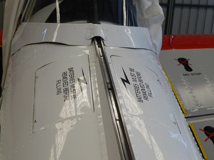
Photo 16. The original battery installation is seen here; two identical access panels mounted on the upper rear fuselage directly behind the canopy.
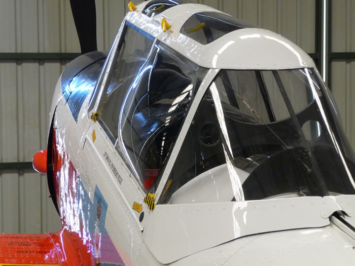
Photo 17. While the thicker canopy framing isn’t very evident here, the bulged rear side panel certainly is! The yellow/black striped handles are the side panel releases, mounted on the forward corner of the front panel and the rear corner of the aft side panel. Note also the yellow canopy handles on the top LHS side; these are more or less parallel to the direction of flight while the matching internal handle is mounted at 90º (just visible through both top glazing panels).
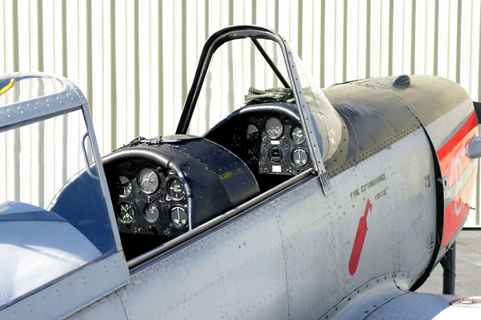
Photo 18. A rather worn-looking T.10. The broader cross-section of the windscreen (it looks both more squat and “flatter” on top) is evident when compared with Fig.2. Note also how the lower edge of the windscreen is now curved, while the canopy rails are actually on the cockpit sill (on the Canadian-built Chipmunks they're lower down, recessed into the fuselage side). Both coamings extend aft of the instrument panel by some 9”, and curve down and aft. The eagle-eyed amongst us will note the lack of longeron strengthening plates behind the cowling – this aircraft left the RAF in 1974 and operated under the Experimental category in the USA and thus escaped the mandatory modification – at least until CASA caught up with it on its arrival here!
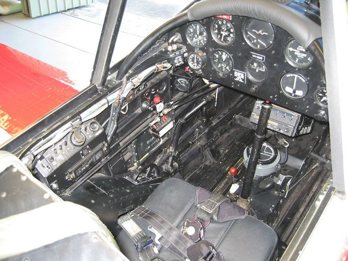
Photo 19. The “coal hole” – there is very little colour here. The camera has washed out the colours – the seat cushion and crash padding on the coaming really are black too! The radio installation, above the surprisingly conspicuous floor-mounted compass, is a modern addition.
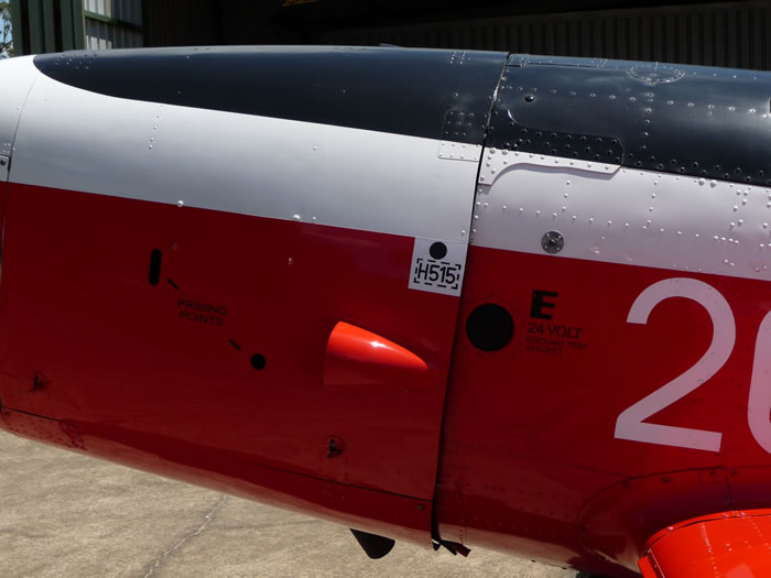
Photo 20. This photo shows the circular black bakelite (?) ground power plug. Also visible are the priming access holes on the LHS cowling and the “T”-shaped longeron strengthening plates immediately aft of the cowling.
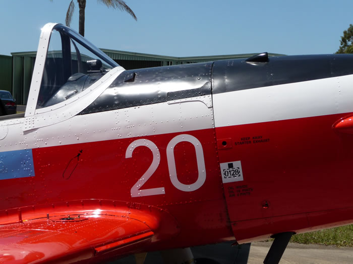
Photo 21. Intended to show the cartridge starter exhaust (above the square white “O128” marking), this photo also shows the longeron strengthening plate, how the lower edge of the windscreen is curved and the later style (“Canadian”) exhaust.
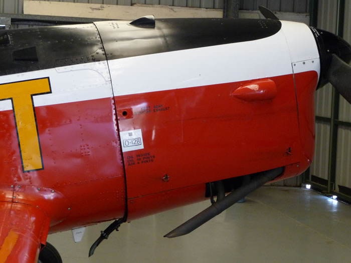
Photo 22. This is the original sloped (and subtly thinner) exhaust pipe, which exits the cowl through a substantial cut-out. Oddly enough, the aircraft sounds different with this exhaust! The curved oil drain is non-standard.
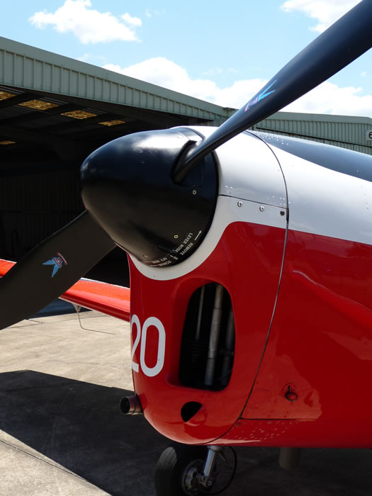
Photo 23. This is the standard smooth spinner, with the join line (and screws) at the backplate. This Chipmunk has the “Canadian” exhaust/cockpit heater set-up, note the protruding intake on the lower RHS of the cowl. The “cupped” intake (below the larger air intake) is standard for all UK-built aircraft, replacing the vertical “slot” arrangement the Canadians used. Notice the different shape of the large air intake; the outboard lip sweeps down and aft - compare this with Photos 6 & 13.
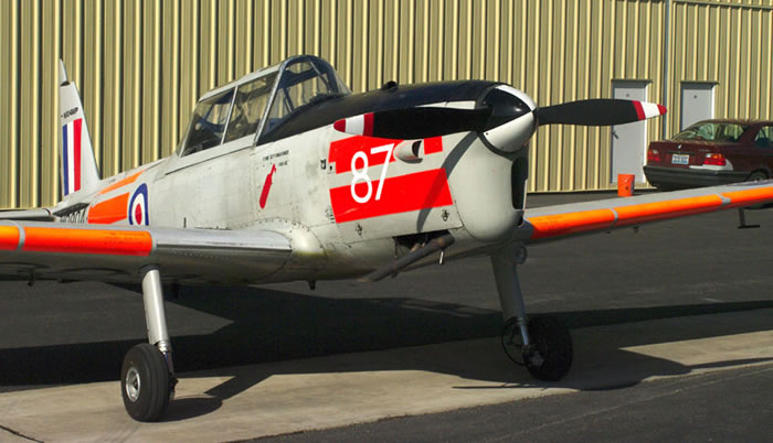
Photo 24. Plenty of details here: “T”-shaped pitot mast, landing light of the LH leg only, the long-span stalling strips on the wing leading edges and no heater (indicated by the lack of the protruding tubular intake on the cowl nose and the sloped exhaust stack. As VH-QOZ, this aircraft only survived for 12 months in Australia, being written off in January 2012.
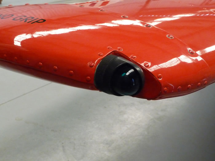
Photo 25. This is the rather neat nav light installation. The entire assembly appears black; the green (or red) lens colour is not apparent when viewed from any distance exceeding a few cms.
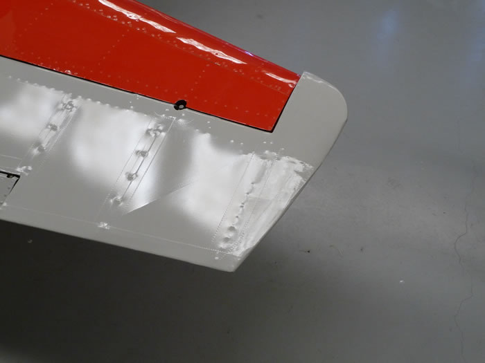
Photo 26. The elevator horns are subtly (approx 1.5 inches) wider than those on the DHC-1A – compare with Photo 4.
Photo 27. The revised, repositioned and larger LH battery access hatch introduced in 1972. The RH hatch remained unchanged. Also apparent here are both the lack of the “V”-shaped plate on the fuselage frame doubler and also the channel for the canopy rail (as fitted to Canadian-built Chipmunks).
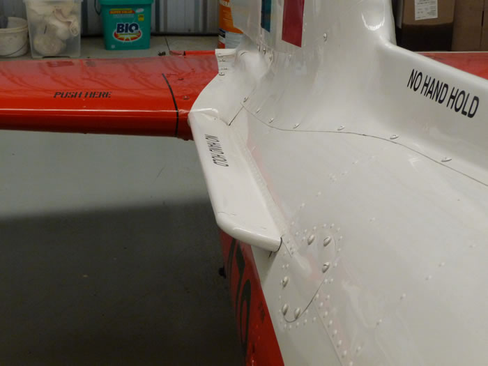
Fig.28 Another view of the strakes - actually they're spin recovery strakes, although DH called them "anti-spinning strakes". Note that they're mounted perpendicular to the fuselage, i.e. they were not horizontal / parallel to the tailplane, giving a messy join with the tailplane leading edge.
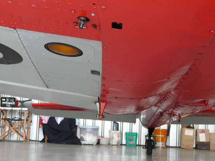
Photo 29. The rarely seen Chipmunk “nether regions” – the downward identification lamp under the RH wing (the area outboard of the panel line is fabric covered). The flush vent is also visible lower centre/RHS of the picture.
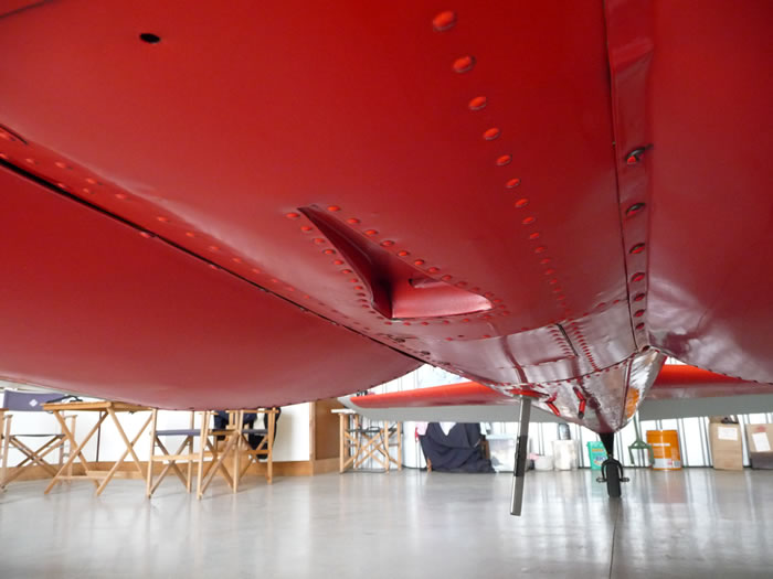
Photo 30. A close-up of the NACA-type vent, located on the fuselage centre-line. The often overlooked “gull wing” effect is also apparent here.
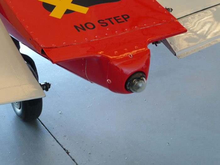
Photo 31. The subtly more pointed and longer tailcone is because UK-built aircraft had an additional fairing to accommodate the nav light – compare with Photo 3.
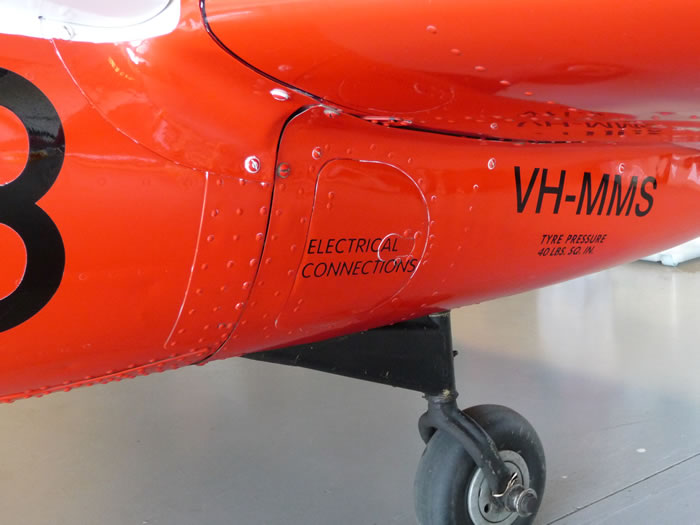
Photo 32. Electrical access panel on tailcone LHS, beneath the tailplane.
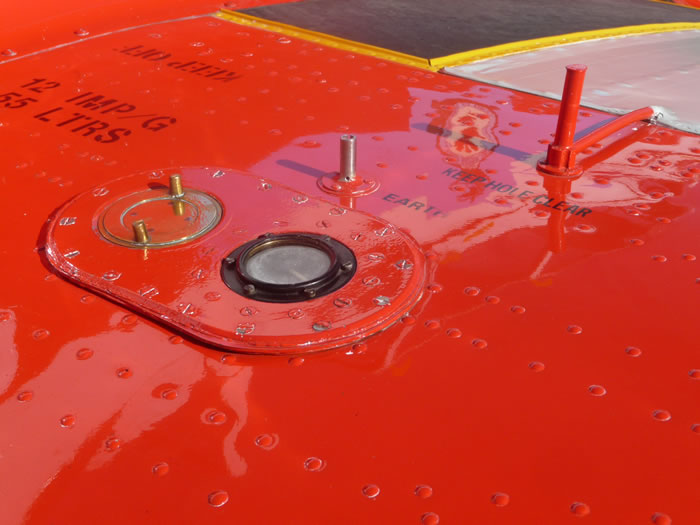
Photo 33 The rather less than aerodynamic fuel cap/gauge assembly on UK-built Chipmunks. Note their reversed positions and fuel vent assembly/earthing point directly behind. The polished brassscap is purely owner conceit; in RAF service they were dull if not painted. Compare this with Photo.6.
Some of these have been privately owned now for 45 years, and as such many non-standard items have appeared. For example, all four “tail feather” variants (no strakes/narrow rudder, no strakes/broad rudder, strakes/narrow rudder and strakes/broad rudder) can be seen. Another common variation is that many are fitted with Hoffmann wooden props, which have broader/square-tipped blades, as well as a seamless one-piece spinner. So check your reference photos!
Copyright 2017 by Rod Blievers
Page Created 30 March, 2017
Last Updated
30 March, 2017
Back to Reference Library
|
 Home |
What's New |
Features |
Gallery |
Reviews |
Reference |
Forum |
Search
Home |
What's New |
Features |
Gallery |
Reviews |
Reference |
Forum |
Search