|
Focke-Wulf Fw 190
Main Landing Gear
Part Two - 1/48 Scale
Model Issues
by
Robert Stephenson and
E. Brown Ryle III

HyperScale is proudly supported by
Squadron.com
Once Bob got to
work on the specifics of the different manufactures Fw190 model
gear, it quickly became clear that the only way to really settle the
1/48th scale accuracy issue was with actual measurements
of the Fw190 landing gear. I made a phone call to Malcolm Laing.
We needed
measurements that would apply to a model. Simply having Malcolm
measure the gear from end to end or end to wing wouldn’t give us
what we needed because of the differences in the way the real gear
installed and the way the model gear attaches.
We settled on a
measurement from the point where the gear leg emerges from the wheel
well to the center of the top link pivot point. We realized that
trying to measure to the axle center would be unreliable. The strut
is compressible and the overall length of the gear would vary
depending on the weight of the aircraft and the internal pressure of
the strut (as prescribed on the pressure chart painted on the
Fw190’s landing gear cover).
At the end of the
week Malcolm provided a hand drawing with the Fw190 landing gear
measurements. I emailed this information to Bob and he took it to
the hobby bench along with his micrometer.
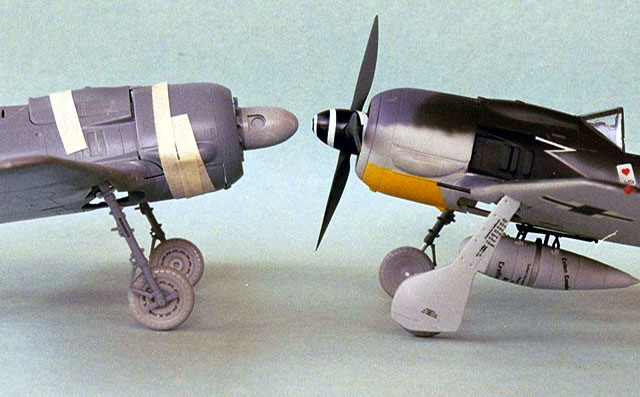
The three 1/48th
scale Fw190 landing gears in question were: the DML/Dragon (L), the
Trimaster, (M) and the Tamiya (R). (Photo 10) I decided to
determine how the gear legs compared with each other, then with our
actual measurements.
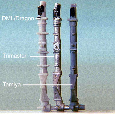
Photo 10
I tried to
measure the gear legs in the Fw190 models I had already built. This
method was unreliable. It was too difficult to get my calipers into
position and get repeatable results.
I broke out my
un-built kits and tried another approach. I marked each leg with a
marking pen and installed them in their respective wings. The legs
were marked at the point where they emerged from the wheel well
using a 20x jeweler's loupe and a sharp scriber. I tried to get
reliable measurements by using my calipers but again I considered
the results untrustworthy.
At my job we have
a really cool measuring system that we use to check our close
tolerance work. Basically, it’s a microscope/ video/ computer
measuring system. It will magnify a .025 drill bit to about 5
inches on the video screen and measure in three dimensions
calibrated to .0001. By hovering the
crosshairs over the points to be tested and clicking the mouse the
computer will do all the trig or geometry and produce the sizes.
While I didn’t use all the available amplification, it did give me
highly reliable measurements:
Wing
Bottom Top Link Retraction Strut
Point Axle Center
Tamiya .786 in.
(19.96 mm) .421 in.
1.179 in.
Trimaster .764 in.
(19.41 mm) .439 in.
1.183 in.
DML .819
in. (20.80 mm) .465 in.
1.226 in.
Real Fw190 .817 in.
(20.75mm)
Included is the
distance from the wing bottom to the center of the axle. This was
done for comparison purposes but because of the reasons listed
above, this distance will be variable on
a real Fw190. The wing bottom to retraction strut point is also
included for comparison purposes.
The DML leg is
almost exactly right. The Tamiya is .031(.79 mm) short. The
Trimaster is .052 in. (1.32 mm) short.
Overall, from
wing to axle, the DML is .047 in (1.19 mm) longer than Tamiya and
.043 in. (1.09 mm) longer than Trimaster. So, why the big
difference in stance when the models are displayed on the table?
There are several factors.
The main reason
for the large difference in the kit’s stance lies in the way the
kits are engineered. The Trimaster/DML/Dragon and the Tamiya
landing gears do not assemble the same way.
The Trimaster and
DML/Dragon gear have difficulties: When assembled, the legs have
almost no forward rake. Further, installing the DML/Dragon
wheelwell insert can be troublesome and incorrect part placement
will create additional problems. (Photo 11).
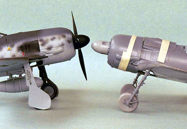
As far as we can tell, this DLM/Dragon problem, resulting in
pointy-toe landing gear with no forward rake, is where the rumor got
started about the Tamiya landing gear being short.
DML (no
correction) Tamiya (no correction)
Photo 11
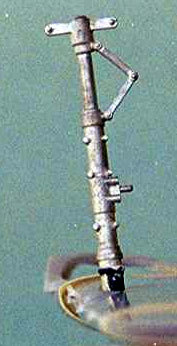
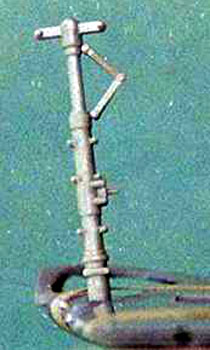
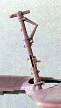
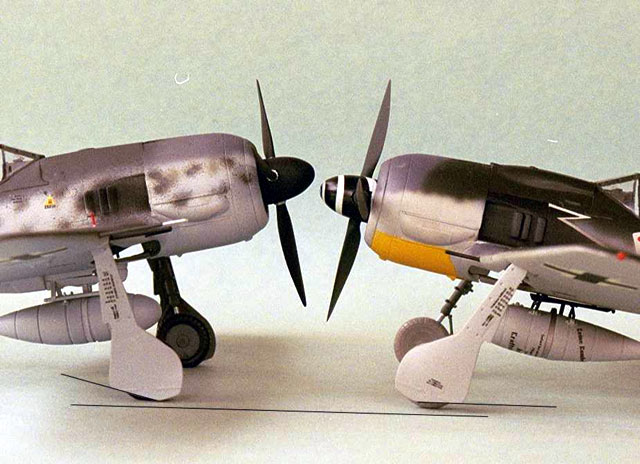
Installed
without any modifications, the gear on the Trimaster and DML/Dragon
hang almost perpendicular to the bottom of the wing. (Photo 12,
TRIMASTER, and Photo13, DML leg) The gear should rake forward about
15 degrees from a line drawn perpendicular to the centerline of the
fuselage. (Photo 14 Tamiya leg)
Photos 12, 13 & 14
As mentioned previously, a good visual
clue that the gear is raked correctly is the bottom of the gear door
should run parallel to the ground. (Photo 15).
DML (no
correction) DML (corrected)
Photo 15
Although the Trimaster gear is metal,
it presents less of a problem than the DML gear. When DML changed
the legs from metal to plastic they also lengthened them. As the
measurements show, this is not really a problem, but the drag link
part that accompanies the DML kit was not lengthened. This does
create a problem.
The
Tamiya gear goes together without much trouble. While this is
great, and Tamiya kits are known for their ease of assembly, not all
of it is cake. The gear stance, if you simply assemble the gear, is
not guaranteed to be correct. You must take your time and ensure
that the gear is aligned to the proper forward rake.
Another
small contributor to the different in kit “stance” is wheel (tire)
size. Trimaster/DML wheels are .585 in. (14.86 mm) while the Tamiya
wheels are .545 in. (13.84 mm). This means a .020 in (.51 mm)
addition to the Trimaster/DML kits. The correct Fw190 wheel size in
1/48 scale is .574 in. (14.58 mm). So, the Tamiya wheel is slightly
undersized.
Also, all of the
kits are blighted by what resembles a big square knot at the top of
the strut (?). (Photo 10, top of all struts) As it’s not on the
real a/c, you’ll want to at least reduce it in size for a
better-looking part.
Trimaster
The first thing
you want to do on the Trimaster kit is thin the edge of the wheel
well cut out in the wing. This is simple, gives a more realistic
appearance and helps with assembling the landing gear.
You’ll also have
to do a bit of plastic removal on the outside of the wheelwell
insert for the proper clearance of the upper wing and the wing
leading edge. Test fit the wing halves with the wheelwell in place
until you’ve removed enough material for a good fit.
I strongly
suggest you cheat the wheelwell forward a bit. This will allow you
the necessary room, to correctly attach the gear drag links to the
motor face in the main spar. If you position the wheelwell too far
aft in the wing opening, the drag link part will not connect when
you attempt to glue it into place in the wheelwell part. Again,
test fit.
Once you get the
wheelwell to fit into the wing, and moved it far enough forward,
make sure that the sockets for the legs are centered (end to end) in
the opening prior to gluing. You can eyeball this or measure from
the outside edges of the wing opening.
To build the
correct landing gear rake, remove some material from the top back
surface of the strut. Removing this material will allow the strut
part clearance into the socket at the correct angle. While doing
this: try not to remove any material from the very top of the
strut.
As mentioned, the
Trimaster strut is already a bit short. While the Trimaster strut
is a bit too short I don’t recommend fixing it. As is, it is only
about .004in (.1 mm) longer than the Tamiya. I don’t recommend
lengthening the Tamiya either because if you get the rake correct I
will look just fine, in my opinion. But if you have a terminal case
of AMS follow the recommendations for lengthening the Tamiya strut
further down the page. Just substitute the Trimaster difference for
the Tamiya. It will be a bit more difficult pull off as the metal
legs will be less forgiving of mistakes than the plastic ones.
Use drawings and
photos as a guide as you work on the proper rake of the gear.
Again, a good visual clue that the gear is correctly positioned is
the bottom of the gear door running parallel to the ground. (You
might want to test fit the gear cover occasionally to check your
progress.) For me, this whole procedure is infinitely more
difficult than mating the wings to the fuselage or the cowling to
the fuselage. I just don’t have enough hands!
After you have
aligned and attached the gear legs, attach the drag link part. It
will just fit. But, if you find that it’s not quite long
enough: follow the up coming notes on the on the DML.
The wheel axle
on the Trimaster is cast at the correct angle. (Photo 16) Just
attach the wheel perpendicular to the ground and align it straight
ahead. But, be sure you metal strut is straight!
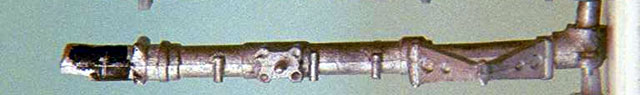
 Photo
16 Photo
16
DML/Dragon
When DML took
over the molds of the defunct Trimaster Ltd., they redesigned all
the cast metal bits in plastic. So, the new plastic strut is not an
exact copy of the metal strut. It is .043 in (1.09 mm) longer with
the additional length at the very top. (Photo 10 of all three
landing gear). This extra length means that when you correct the
rake in the same manner as mentioned for the Trimaster, the drag
links, which were simply cloned from metal into plastic, will not
reach their attachment point on the aft side of the strut. Photo 17
shows a correctly aligned strut with an un-modified link. Once the
link is attached to the strut, it will no longer attach to the
attachment point in the wheelwell.

Photo 17
The link does not
reach its attachemnt point on the motor face in the wing when the
landing gear strut is properly aligned for the correct Fw190 stance.
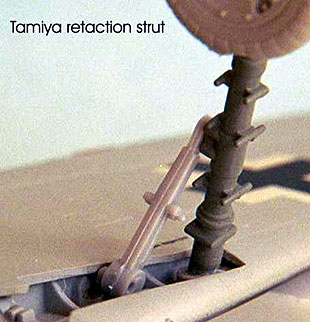
Fortunately, the fix for the DML/Dragon
strut is easy: Cut off the strut’s drag link attachment point and
replace it with .045 in. plastic rod that has been flattened on
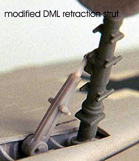
one end to fit against the strut. (Photo 18, DML original strut
vs. DML modified strut). Test fit for length. This part can be
detailed a bit more than I did for this article, but “as is”; it
looks fine in 1/48th scale.
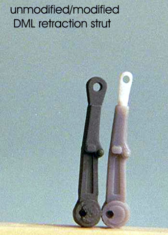
Unmodified (DML Link) Modified
Photo 18
Using a Tamiya link part on the DML will not provide any more
length than an un-modified DML part (Photo 19). A modified DML
part is required for the correct strut rake (Photo 20).
 |
 |
| Too Short |
Correct Length |
Photo 19
Photo 20
Unlike the Bf109, the Fw190 wheels run
almost square to the ground (the wheel top leans slightly outward,
depending on oleo pressure). Further, aircraft, like automobiles,
have a bit of camber and toe-in to the tire. The Fw190 was no
exception. These setting were made by various adjustments in the
Fw190’s gear. But, in 1/48 it’s too small to be an issue.
The wheel axle on the DML/Dragon is 90° to
the strut. It will incorrectly slant the tire when the strut is
correctly canted inwards. You can simply adjust the tire to the
angle it is supposed to be and CA it in place. Or, you can cut
off the axle, drill a hole that will be parallel to the ground,
and install a .045 in. plastic rod axle. I suggest the axle.
Remember to keep the tires perpendicular to the ground and
parallel to the fuselage centerline.
Tamiya
The Tamiya strut is .031 in (.78 mm) short in
comparison with a real Fw 190 part and .047 in. (1.19) shorter
than the DML overall. I’ll go over a couple of different
suggestions for correcting the Tamiya gear but first I must say
that I’m not too troubled by the fact that the Tamiya gear is
short.
The Tamiya gear is shorter from the top
scissors link to the axle by .014 in. (.36 mm) than the DML gear.
This is only .67 in. (17.1 mm) in 1/1 scale! I’m willing to
accept this difference as a weight /pressure issue on the real
a/c. If you feel the gear needs lengthening here are a couple of
ways to go about it.
To lengthen the strut, cut between the drag
link attachment point and the uplock pin. Remember to calculate
and include the thickness of the saw you are using. If your saw
is .10 in (.25 mm) thick, then add that amount to your overall
correction. This will usually add up to between .040 and .045 in.
(1.02 mm and 1.14 mm).
Sandwich the “sized” plastic plug between
the cut, check your alignment, and glue. You can strengthen the
joint by pinning it through the center with sections of a small
drill bit or a bit of straight pin.
Another approach is the one taken by
Ian
Robertson in his D-9 build-up (as posted here on Hyperscale).
Briefly, Ian grafted the upper Tamiya strut with the DML scissors
and axle section. Ian did a nice job, and I suggest you check his
article for the complete story. This method will also give you
some additional overall length.
Personally, I don’t plan to modify any of
my Tamiya Fw190’s landing gear. There is just not that much
difference when you compare a Tamiya kit to a correctly built
Trimaster/DML kit. And, if you replace the undersized kit
tires with some correctly sized after market ones, that is
about all the help needed with the Tamiya’s stance/height issue.
(See Photo 21, correct tires on Tamiya kit vs. DML kit with
corrected strut)
Tamiya (correct size wheels)
DML (corrected strut)
Photo 21
If
you are not inclined to modify the Tamiya kit, the landing gear
assembles almost trouble free. As when building any model don’t
take it on faith that everything will turn out correctly by gluing
parts to their attachment points. Double-check the rake and
inward cant of the gear before making a permanent attachment.
As was said prior: using the gear door as a
guide can help you check the rake and attain the correct stance.
Carefully push and/or pull as necessary.
Another nit-pick item on the Tamiya needing
attention is the wheel axle. It is not parallel to ground after
assembly. Follow the suggestions made to correct the same problem
for the DML/Dragon strut.
|
Gear
Covers - Strut, Attachment and Shape |
One thing that
is not done very well on all the kits is the gear door attachment
studs (Photo #10A). The DML studs are overstated and do not line
up with the holes on the doors. The Trimaster and Tamiya are more
to scale, but are in the wrong position.
Photo 10A
Having said that, I’ll also say that the
placement of the studs may not be much of a problem. On
the real Fw190s the holes on the outside of the doors were usually
patched over with “pinking” (fabric, glued in place, for
areodynamic reasons) and painted over with a red-brown fabric dope
then RLM 76 (or just the red-brown if the covers had been worked
on).
Another thing
is the shape of the main gear cover. While the outline of all the
covers is not so bad as to disqualify your kit from judging at the
local hobby event, those of you possessing a few good photos of
Fw190 gear covers might want to compare those photos to your kit
parts. A bit of time studying and reshaping quickly provides a
more accurate gear cover.
We hope the
real Fw190 landing gear information has been of help. The landing
gear fixes offered here are easily attained by modelers with
average skill or above average patience and persistence. These
minor gear problem fixes will help modelers achieve an accurate
look to their Fw190 kits.
Thank you for
reading the entire article. Bob and I understand that it might be
overkill for such a specific subject but we hope this information
removes some of the urban legends that have surrounded the Fw190
landing gear and these kits for years.
Happy modeling.
J
The aircraft
and aircraft parts photos are owned by Brown Ryle. The model and
model part photos are owned by Bob Stephenson.
Brown Ryle
completed the line drawings for the figures. Please excuse the
poor quality of the drawings. The pencil drawn lines and the
paper on which the drawings were made did not duplicate well into
electronic medium.
The authors
whole-heartily suggest that the reader obtain copies of the
published references for a much better graphic presentation of the
figure’s subject matter.
Fw190 Rivet Manual, dtd 1940
Fw190D Walk
Around
Fw190A/F/G Walk
Around
Return to Part One
Images
and Text Copyright © 2003 by Robert Stephenson
and
E. Brown Ryle III
Page
Created 26 June 2003
Last updated
26 June 2003
Back to HyperScale Main
Page
Back to Reference Index |  Home |
What's New |
Features |
Gallery |
Reviews |
Reference |
Forum |
Search
Home |
What's New |
Features |
Gallery |
Reviews |
Reference |
Forum |
Search