|
Focke-Wulf Fw 190
Main Landing Gear
Part One - Overview and
Operation
by
Robert Stephenson and
E. Brown Ryle III

HyperScale is proudly supported by
Squadron.com
Bob Stephenson and I have been emailing each
other for what seems a very long time. The text is usually split
between the general stuff of life and hobby related material.
Somewhere
among the email Bob mentioned a series of Internet postings on 1/48th
scale Fw190 landing gear asking the question “Which Fw190 stance
is correct? Is it the Trimaster, the DML/Dragon, or the Tamiya?”
According to Bob, the posted answers were more dependent on the
person’s opinion of the model than the study of Fw190 landing gear.
I knew why
there were numerous questions about the stance of the Fw190.
The Fw190 landing gear is not as easy to understand as it appears.
Bob and I
decided to do some research to see what answers we could sort out
regarding these questions. We hope the following will be a good
primmer on understanding both real and 1/48th scale Fw190
landing gear. Please note the changover from my part describing the
actual aircraft gear to Bob’s part of describing and detailing the
nature the model kit gear.
Overview &
Operation
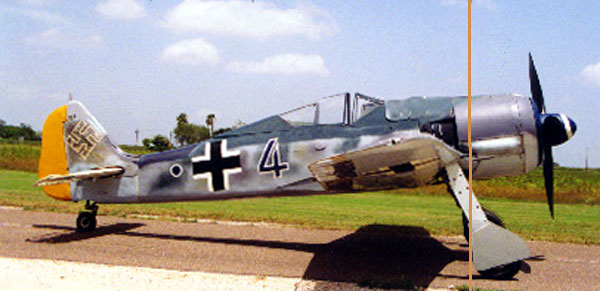
The Fw190 undercarriage is a bit different from the average
fighter landing gear of its time. The Fw190 gear was: operated by
pushbutton control of electric motors in the wings, possessed
electric up- and down-locks, and had a control wire running from the
starboard strut that retracted the spring-loaded tail wheel. The
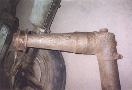
“look” of the gear is also different: when the gear is extended it
has an odd inward cant (Photo 1 below).
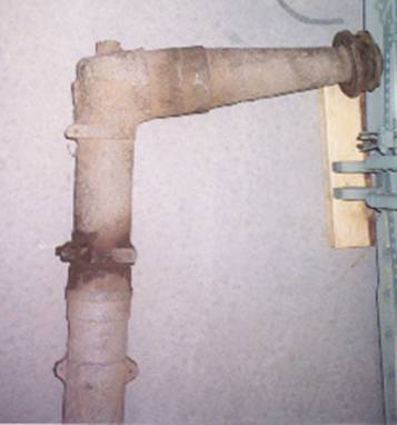
Noticeably, all of the tire is positioned forward of the leading
edge of the wing (Photo 2 below).
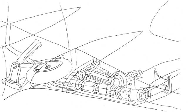
Electric Motor and Folding Drag Links
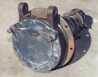
Photo 3
The
front of the electric located motor in each wing. It is mounted in
the wing spar inboard of the strut/wing attachment point and
provides gear extension and retraction.
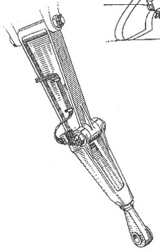
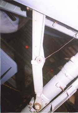
A set of folding drag links (Figure # 1 and
Photo 4), also called radius rods, connect the rotating drive outer
cover (front plate) of the electric motor to the landing gear
strut.
|
 |
 |
|
Figure 1 - folding drag link
|
Photo 4 - rear side of landing gear strut showing drag link
attachment point
|
As the electric motor’s face rotates, the
links extend or retract the landing gear (Figure 2 below).
Figure 2
This is also how the visual indicator rod
protrudes from or recesses into the wing top (Figure 3 below) to
inform the pilot that the gear is up or down. The landing gear had
indicators in the cockpit, but this was an additional, machanical
source of position. Usually, the upper ¾ of the rod was painted
red, and lower ¼ painted white. When the gear was extended, and the
pilot saw white on the bottom of the rod, the gear was locked down.
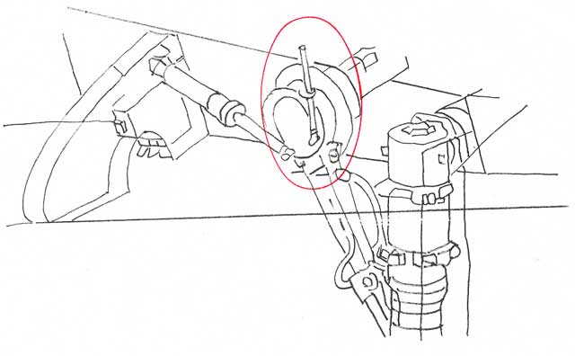
Figure 3
Downlock is provided by electric motor
gearing (1 to 15,000) and a small pressure spring (Photo 5) that
attaches on one end to the rotating face of the electric motor on
the outboard side of the drag link and on the other end to the main
wing spar.
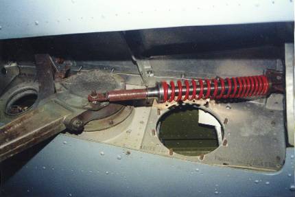
Photo 5
Without this small spring, the gear will
collapse (all modelers detailing their Fw190 wheelwells take note)
as soon as the aircraft is moved and lateral shear is applied to the
landing gear. Uplock is provided by locking units in the wheelwell
that hook onto a small round spur on the aft side of the strut.
Although the gear extends fully for the way
it is designed, it does not extend to a position 90° below the
bottom of the wing. It stops and locks with the gear having an
approximately 13 to14° inward rake as measured from the wing
bottom. This inward rake results in the tire being almost directly
under the electric motor (Figure 4), not the strut attachment
point.
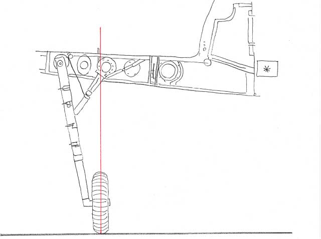
Figure 4
As far as I’ve been able to research the
matter, I know of no definitive answer to the reason for the
gear’s inward rake. You may consider the following while pondering
the design:
a.
The drag links of the landing gear are designed to attach almost ½
the way down the strut. This allows for a very stable strut and
provides great protection from lateral shear. With the size
(length) links they were using, the inward rake may have been
necessary.
b.
Although there is room inside the wing for a larger electric
motor, it may have been decided a smaller and lighter motor, with a
smaller rotating face, could be installed by using shorter drag
links. Don’t think this would have been a bad decision; even the
existing motor, rotating plate, and drag links seem overly strong
for this size aircraft.
c.
Using two points of attachment to the main spar allows the a/c’s
weight to be spread between the strut and electric motor (via the
drag links). This affords dispersal of a/c weight along a section
of the wing spar as opposed to a single point of the wing spar –
which is good. But, the Fw190 main wing spar was rather
over-engineered, so this may not be much of a factor.
Gear & Tire Location
The Fw190 landing gear is located rather
close to the leading edge of the wing. Looking head-on at the wing,
you can easily see the gear cover and especially the tire cover
(Figure 5).
 Figure
5 Figure
5
The
reason the gear is located so close the wing leading edge is that it
is in front of the main wing spar, which is the attachment point of
the main landing gear. But, the spar must also allow room in front
for the diameter of the tire. To accomplish this, the main spar
bends forward as it moves toward the wing tip.
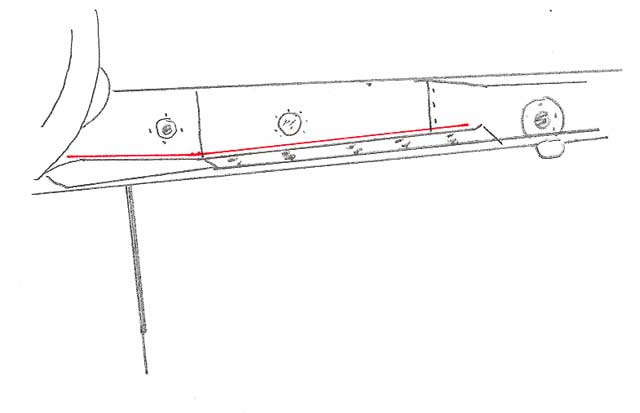
Figure 6 (below) shows the Fw190 upper wing.
The panel line over the location of the aft section of the wheelwell
is the main spar/rear wall of the wheelwell. Note that the panel
line angles forward as it proceeds outward toward the wingtip.
   Figure
6 Figure
6
The spar bends forward far enough to provide
attachment of the strut and clearance of the tire while the
landing gear remains perpendicular to the fuselage. This is
different from other wing spar/landing gear configurations of the
time, but it works well.
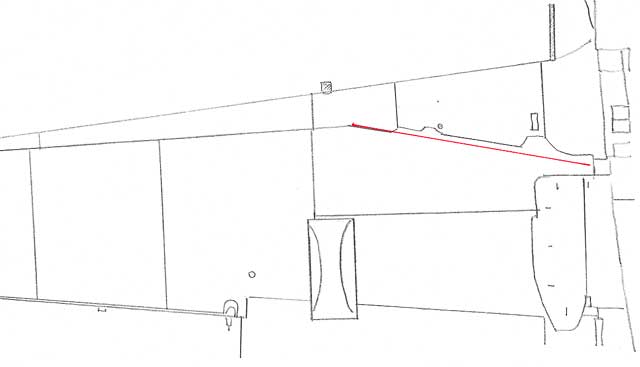
The wing’s leading edge extension at the
wingroot and the wheelwell area through the fuselage allow the
gear’s close position to the wing’s leading edge. When the gear is
in the up position, the strut is stowed inside the wing while the
tire is stowed inside the wing leading edge extension and the
fuselage (Figure 7) - with little room to spare.
Figure 7
[Ever notice that the bottom of the cowling
ammo boxes (Figure 4, right side *), located in fuselage wheelwell
area, are lower at the center of the fuselage than they are toward
the outer edge of the fuselage? That angle is because they were
designed to “just fit” over the retracted main landing gear tire,
which is positioned inside the fuselage at the same angle.]
As I mentioned,
the close location of the gear to the wing’s leading edge, and the
Fw190 wing’s taper toward the tip, moves the tire forward of the
wing leading edge when the main gear is extended (Photo 2). This
forward rake also results from the fact that the strut does not
rotate directly downward from its wing attachment point in the spar.
Strut
The wing
attachment point at the top of the strut (the bend) is NOT 90° to
the gear leg. The angle is approximately 95°. This slight bend can
be seen in the strut drawings (Figure 8), the arrangement of the
strut attachment point in the wing (Figure 9), and in Photos 6 and 7
of the strut.
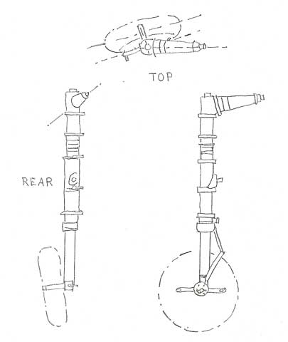
Figure 8
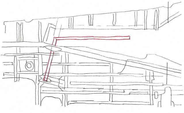
  
Figure 9
Click thumbnails below
to view larger images of Photos 6 and 7:
Further:
1.)
Look at the upper section of the landing gear cover (Figure
10, right side). Notice that the very top of the landing gear
cover, where the strut attaches to the main spar, bents forward.
This bend on the upper portion of the cover fits inside the wing
when the gear extends. The rest of the landing gear cover is
outside the wing when the gear is extended.
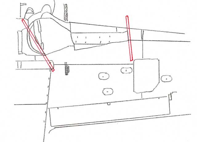
Figure 10
2.)
Look at any photo of a Fw190 on the ground in which you can
see the bottom, aft edge of the landing gear cover (Photo 8).
Notice that the bottom of the cover is cut at an angle parallel to
the ground (Figure 10, left side) when the gear is extended. This
cut is necessary for ground clearance and it varies in size,
depending on Fw190 dash number, and the installation of the inner
gear door (Figure 11). Also notice (Figure 10, left side again)
that this cut is NOT perpendicular to the landing gear strut.
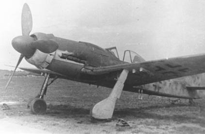
Photo 8
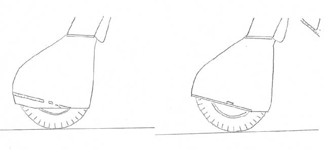
Figure 11
To be Continued
Images
and Text Copyright © 2003 by Robert Stephenson
and
E. Brown Ryle III
Page
Created 18 June 2003
Last updated
19 June 2003
Back to HyperScale Main
Page
Back to Reference Index |  Home |
What's New |
Features |
Gallery |
Reviews |
Reference |
Forum |
Search
Home |
What's New |
Features |
Gallery |
Reviews |
Reference |
Forum |
Search